INKJET-DYING SYSTEM FOR ROLLED METAL
A single-pass printing complex for integration into coil-coating facilities for printing on metal substrate with a white paint applied on the surface; a single-pass printing complex consist of four digital units: each digital printing unit provides one of four basic CMYK colors (Cyan, Magenta, Yellow, blacK); each print unit includes 48+ Epson/Ricoh/Kyocera series print heads and a set of DPS Innovations drive electronics to ensure high accuracy printing position with respect to the main production line.
The complex is equipped with a continuous ink supply system, UV-LED curing system and PC-based control station with a file preparation and color correction (RIP) program.
The complex is equipped with a continuous ink supply system, UV-LED curing system and PC-based control station with a file preparation and color correction (RIP) program.
TECHNICALS PARAMETERS AND REQUIREMENTS
| Unit: | Single pass printing unit with Continuous Ink Supply System (CISS) |
| Print heads model: | Epson S3200 (optional Ricoh/Kyocera series) |
| Print heads quantity, Epson S3200 | 48 pcs |
| Units | 4 pcs, printheads per unit, Epson S3200 – 12 pcs |
| GS support | 3 level |
| Line printing speed | 30 meters per minute |
| Printing resolution | 600dpi |
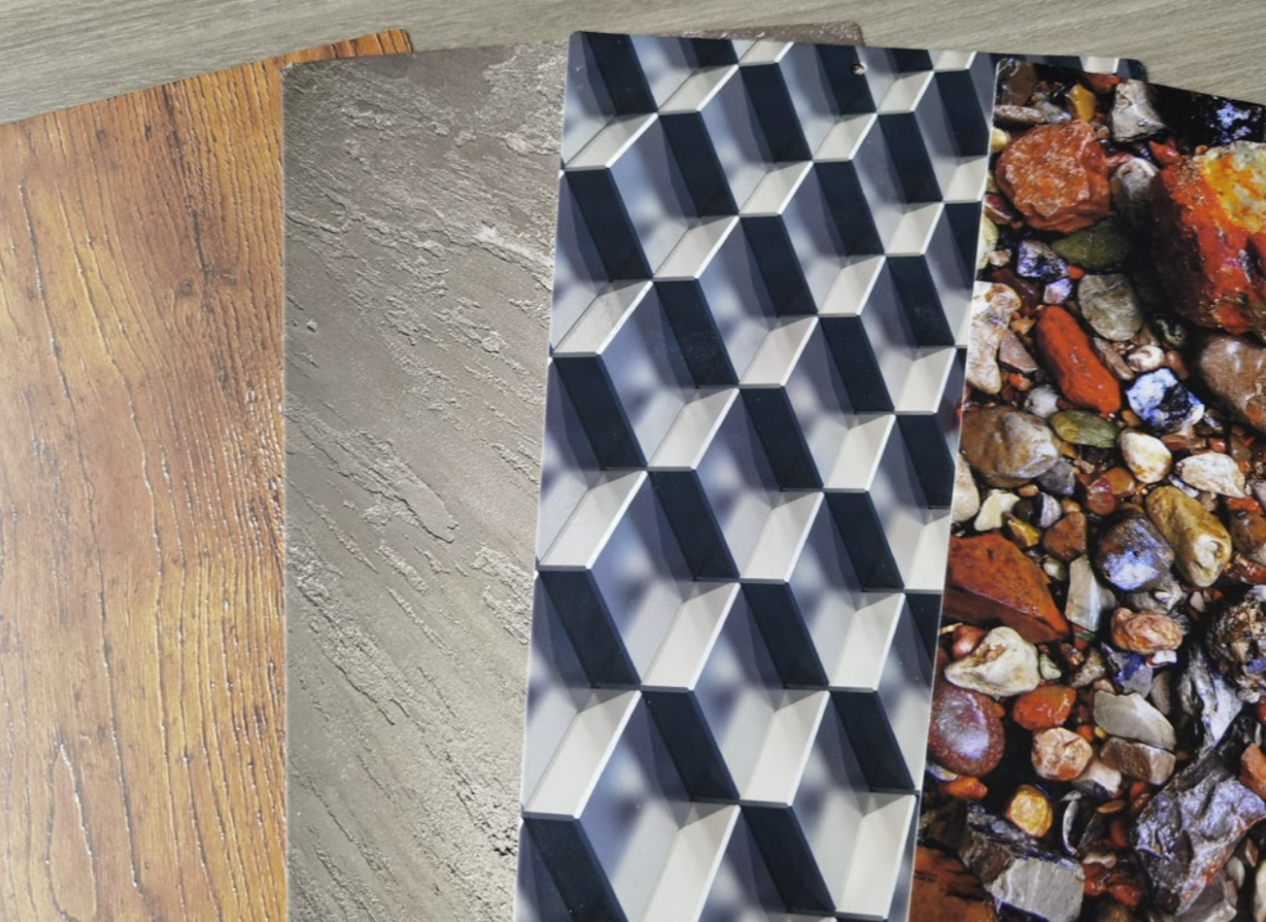
| Substrate | Metallic substrate with the white powder paint applied on the surface |
| Printing width | 1300mm |
| Curing system | UV LED curing |
| Color scheme | CMYK |
VISUALIZATION AND DESCRIPTION
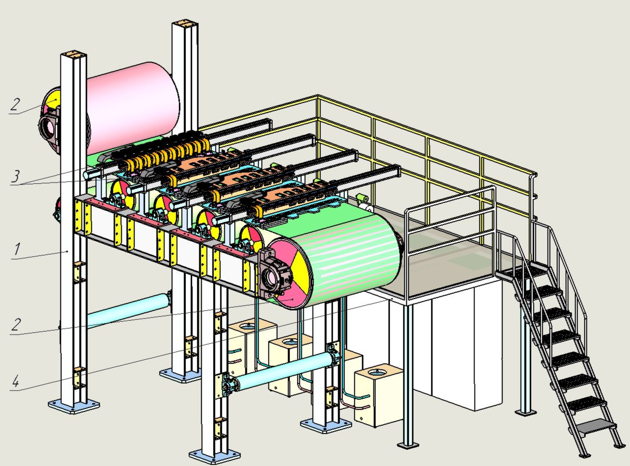
The system for direct application of a color image to metal substrate with applied white paint on assembled into a polymer coating unit and consists of:
- Space frame
- By-pass rollers
- Four basic digital printing units
- Service platform
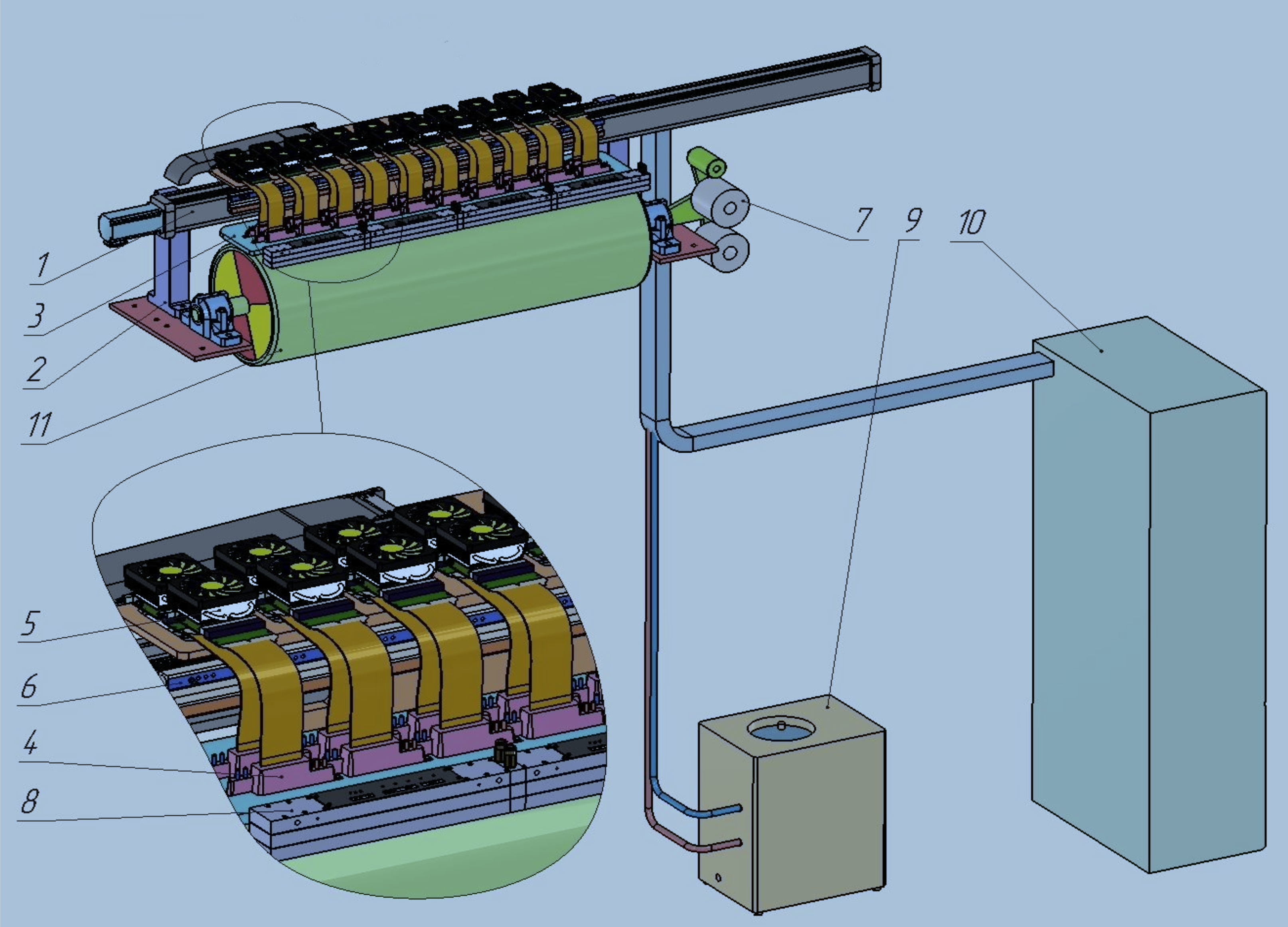
The basic digital printing unit consists of the following main units:
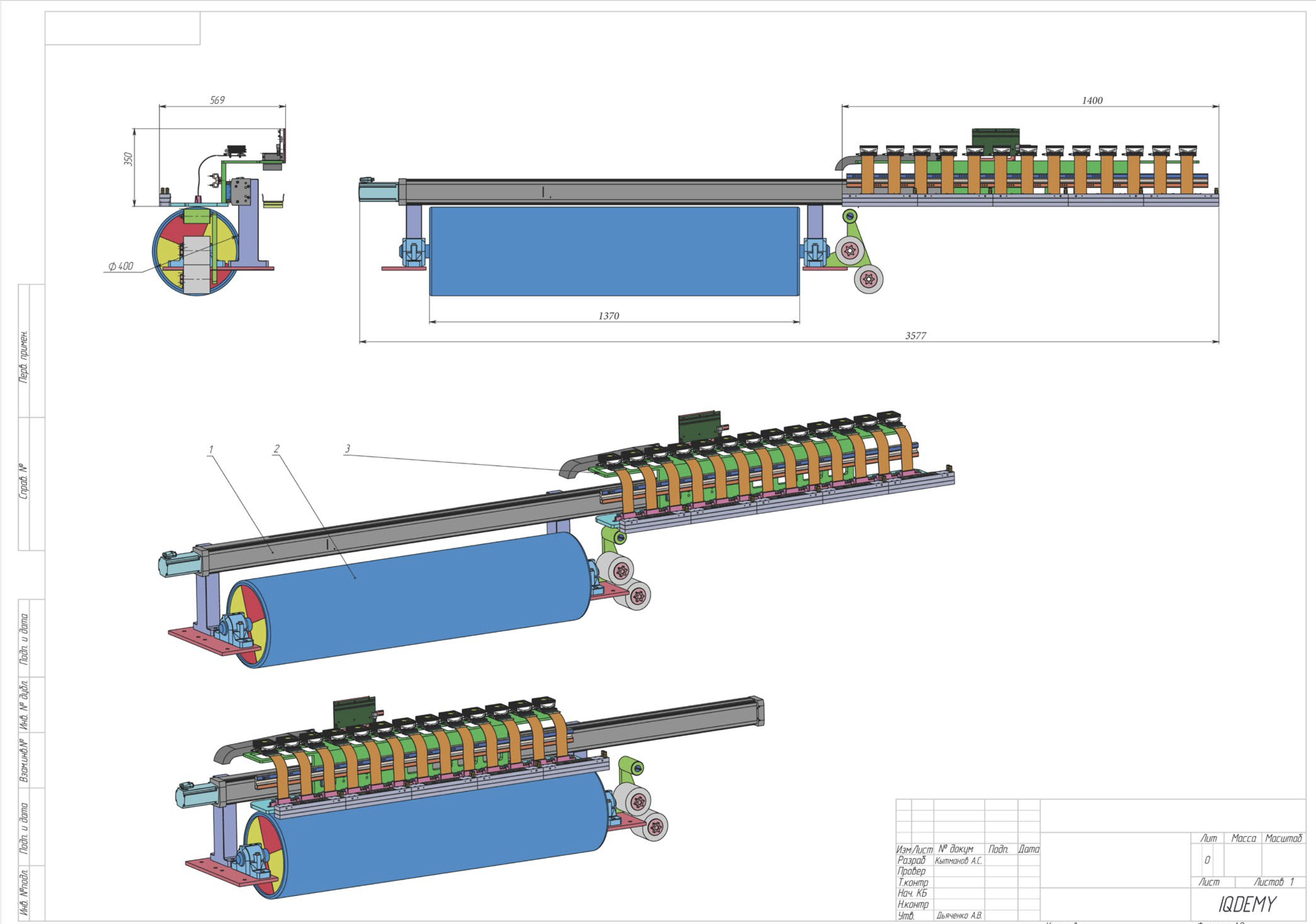
1. The beam. A structural element for holding the head unit (via lifting mechanisms) and the cleaning parking unit over the working field.
2. Lifting mechanisms / Axes of movement along Z. Two axes resting on a beam and changing the position of the printhead unit relative to the Z-axis. Serve for setting the working position, cleaning position and parking position.
3. Printhead unit. Serves for installing and adjusting printheads, installing subtanks, installing a material sensor, control system (data transfer) and some other minor elements.
4. The print head. The main printing element provides the application of the image on the material. A non-separable device that includes a nozzle plate, piezoelectric elements, a heater, a temperature sensor, ASIC chips for controlling piezoelectric elements, an ink supply path, fittings for connecting ink supply pipes, electrical connectors for connecting to a head driver.
5. Print head driver. An electronic device that generates electrical signals for the printhead and provides heating and temperature stabilization of the printhead.
6. Ink supply system. Provides pressure and temperature parameters at the inlet and outlet of each of the printheads.
7. Capping/cleaning/parking unit. It is used to collect ink when cleaning heads, a viper to remove ink from the surface of the printhead and save it for conservation.
8. UV LED curing system. Designed for curing UV-curable inks. Liquid-cooled LEDs are used.
9. UV block cooling system. It is a closed system for circulating the coolant through UV blocks, a circulation pump, a coolant cooler, an air-cooling fan of the cooler radiator.)
10. Control cabinet. Includes a main control computer for preparing print data, controlling the printing process and interacting with external systems.
11. Support shaft. Designed to compensate for material deformation in the perpendicular direction to the plane of the material, directly under the printheads.
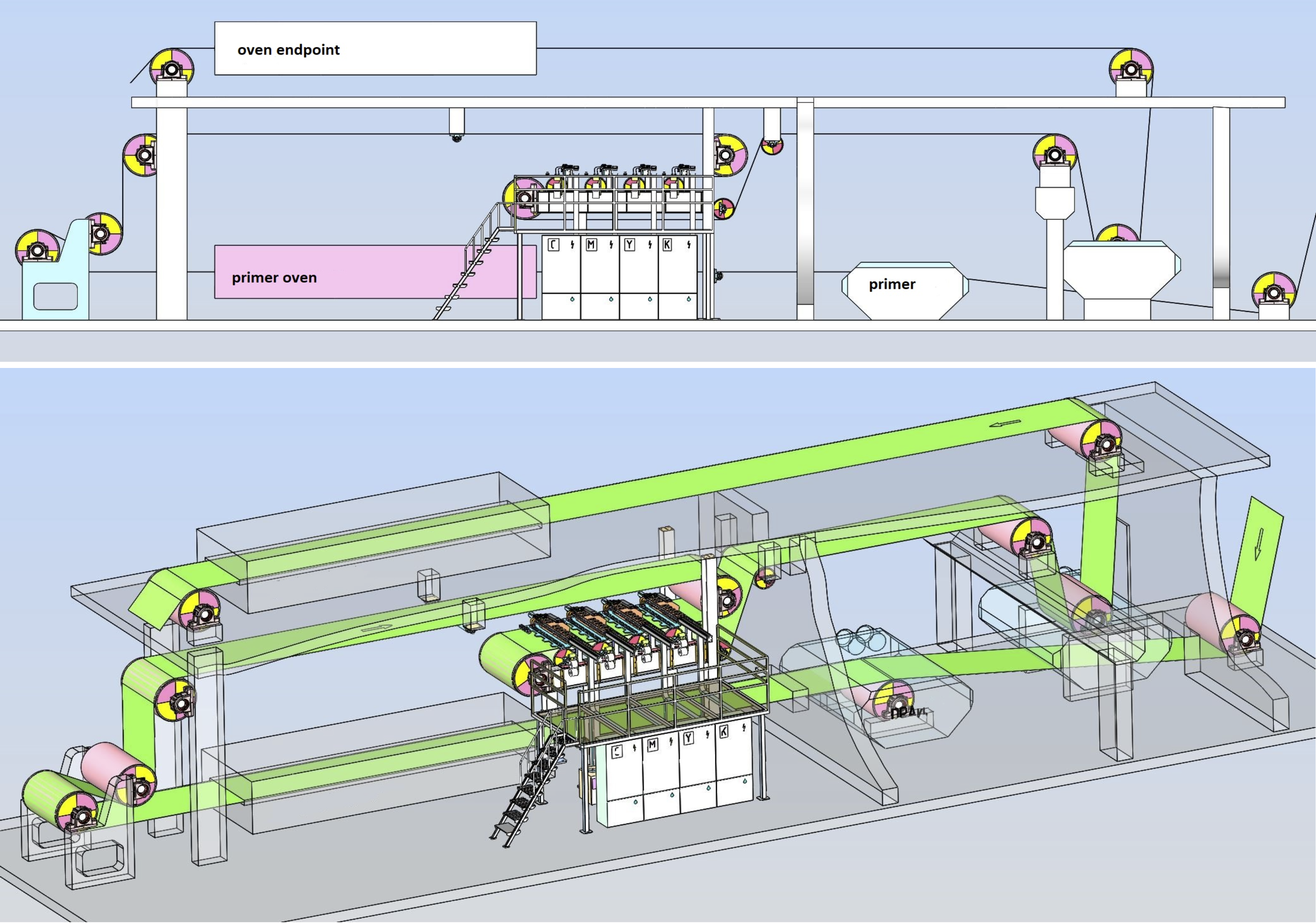
Layout of digital printing complex in the coil-coating line:
Approximate dimensional drawing: